HMI Module Series
Our HMI control module series includes three distinct lines—Streamlined, Standard, and High Performance—each tailored to meet specific embedded system needs. The Streamlined Series offers compact, efficient modules for essential functionality; the Standard Series balances versatility and performance for everyday demands; and the High Performance Series brings advanced control to the most demanding applications.
Streamlined
To be included in products where functionality and cost-effectiveness meet. These modules offer intuitive user interfaces and optimized functions.
Standard
For products to support essential functionality, featuring user-friendly interfaces, clear visual displays, and efficient controls.
High Performance
To be included in products where support is needed for complex systems, boasting lightning-fast response times, exceptional graphics quality, and intuitive user interfaces. Open-source Linux operating system distribution.
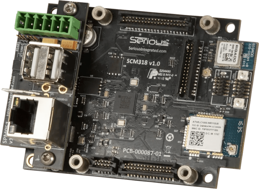
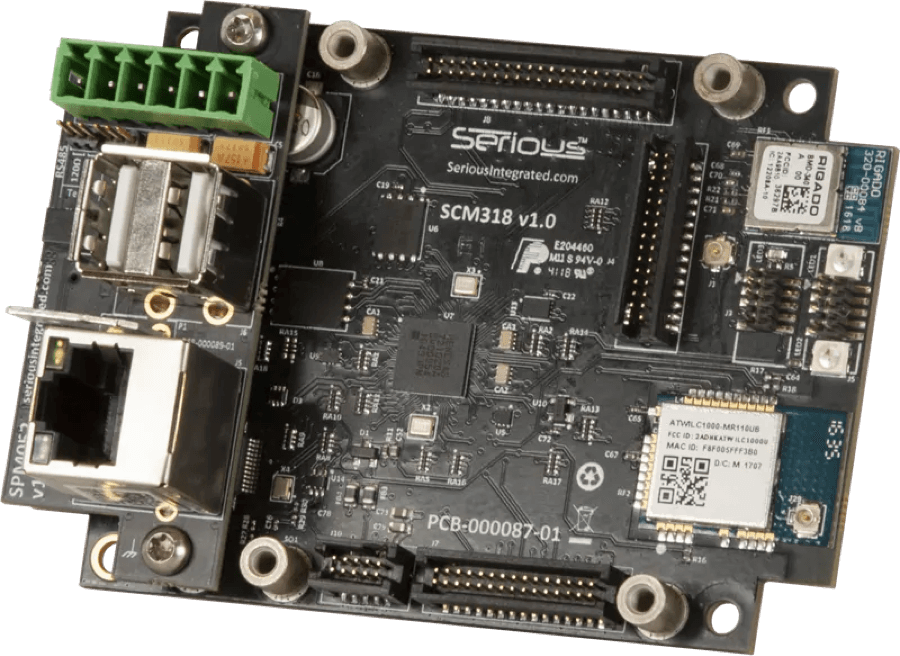
Comms/Control Module for Embedded Systems
The SCM318 series is an off-the-shelf comms/control module delivering the processing and communications scalability you need for your next generation of embedded systems. Whether you need to connect with wired or wireless networks, you can choose a low-end version with just processing and basic RS485 connectivity, or higher-end units with WiFi, Bluetooth 5, Ethernet, or other features to link your device to the outside world.
Main Benefits
Cost-effective
Off-the-shelf ready with distribution support
Robust & comprehensive
Software & hardware deployed in multiple markets/industries
Reduced time to market
Flexible LCD/CPU/comms
combinations for the right price/
performance/features
Customizable
e2ip technologies team offers
customized solutions based on core
products
Industries Served
Industrial
Medical
Aerospace
Manufacturing
Design Support
We bring your vision to life with expert design support, from initial ideas through to fabrication. Backed by industry expertise and supported by a robust network of partners, we make sure your interface is as powerful as it is precise. Our dev kits, tools, software and accessories provide everything you need to create a seamless touch experience tailored to your needs—just tell us where you want to go.
Dev Kits
Our Development Kits provide everything you need to get started. With all the necessary embedded system software downloads and documentation included, you’ll have the resources to quickly get up-and-running.
Tools & Software
Leverage the HMI Modules with integrated firmware and development tools.
Accessories
SPA is designed to allow easy access to USB and/or JTAG signals on these SIMs without the appropriate physical connectors.